To implement all the logic gates and operate the DC load with the help of Push to ON & OFF switch and a switching relay
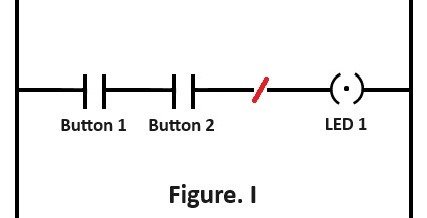
( NAND Gate Implementation )
Components
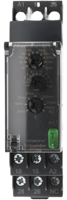
Relay
 rotate.png)
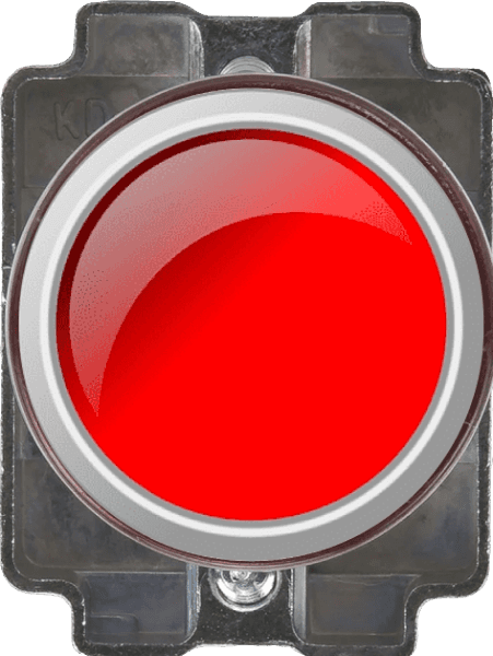
Push to ON
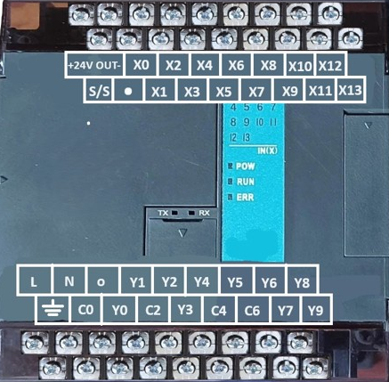
PLC
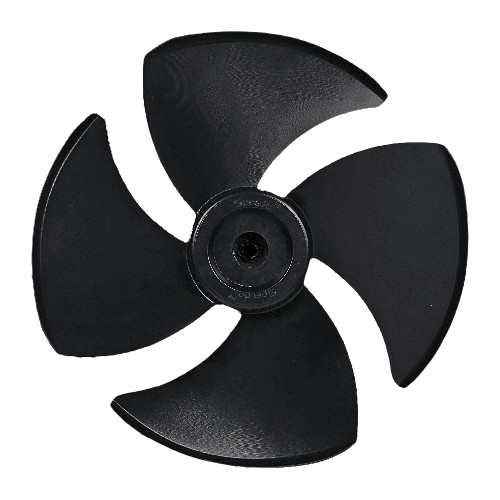
DC Load

Supply

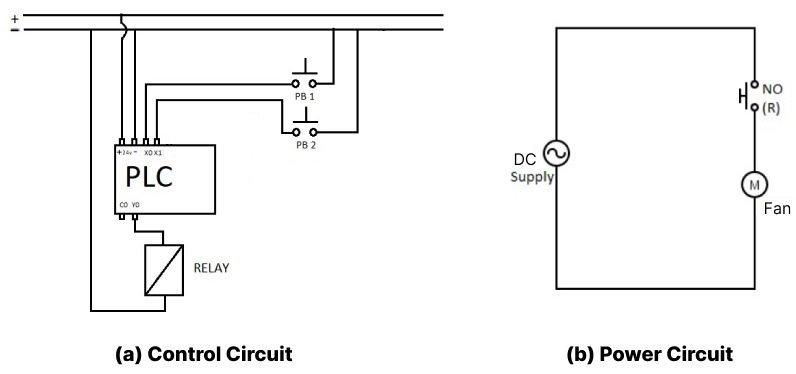
Control circuit
PLC
4C/O Relay 12V DC
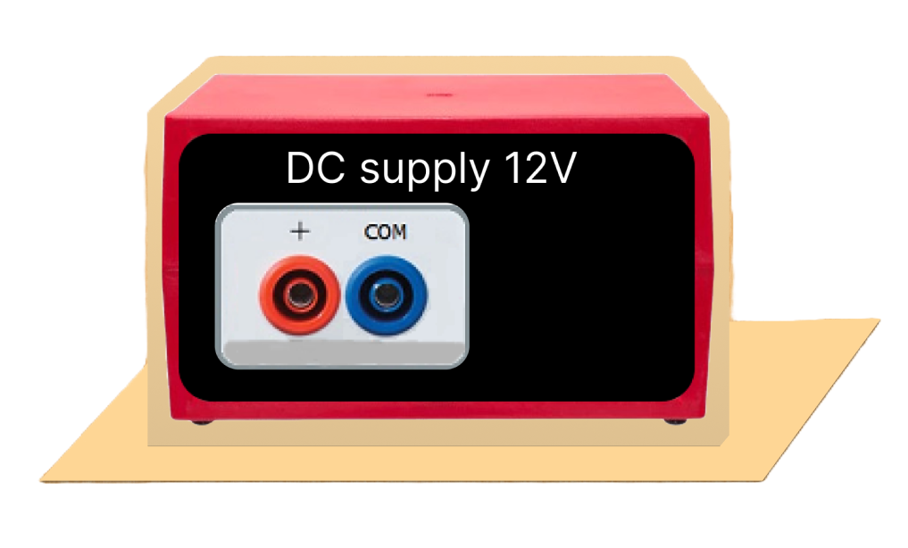

DC supply 12V

X0
X1
Power circuit
DC supply 12V
No (R)
Control Button
.png)
FAN (DC Motor)
Instructions
1. Click on the Control Circuit button in Control Circuit Section.
2. Get the required components in Control Circuit Section by clicking on components displayed in Components Section.
3. Establish the connections according to the control circuit diagram provided in Fig. (a).
4. Verify the control circuit by clicking on the Check Connections 1 button.
5. If Wrong Connections, click on the Delete Connections 1 button to delete connections and make the right connections.
6. Once the Control Circuit is verified, click on the PLC to design the ladder logic.
7. A new window will appear for the ladder logic. Design the ladder logic using the instructions tab on the PLC window.
8. Once the ladder logic is verified, switch to the Power Circuit Section. Make the connections according to the Power Circuit diagram provided in Fig. (b).
9. Click on the Check Connections 2 button to validate the Power Circuit.
10. If Wrong Connections, click on the Delete Connections 2 button to delete connections and make the right connections.
11. Once the Power Circuit is verified, switch on the Power Supplies & enable the Push Button by a mouse click.
12. Click on the Print button to get a print of the webpage.
13. Click on the Reset button to refresh the webpage.
[🔴 Red Endpoint Denote Positive terminal.]
[🔵 Blue Endpoint Denote Negative terminal.]
PLC Ladder Logic.
Components

NO (OFF)

NO (ON)

NC (OFF)

NC (ON)

Coil (OFF)

Coil (ON)
Y0

Led
X0
Button 1
X1
Button 2

Inverse
Instructions
1. Click on a black placeholder on the webpage to add a symbol.
2. A dialog will appear where you will write the symbol name (e.g. a , b , c).
3. The symbol will be placed in the selected location according to the logic gate Fig(i) provided.
4. Repeat the process for each placeholder to complete the ladder logic as shown in the Fig(a).
5. If you make a wrong connection, click on the Delete Connections button to remove the wrong connection and make the correct one.
6. Click on the Check Connections button to verify that all connections are correct.
7. Ensure the connections follow the structure shown in the Fig(i)
- a, b for NO , NC respectively.
- c for the relay coil.
8. Verify your connections by comparing with the reference Fig(i)