To design a logic for starting a 3-phase Induction Motor by Direct on- Line (DOL) Starter.
Components
AC Load

Relay
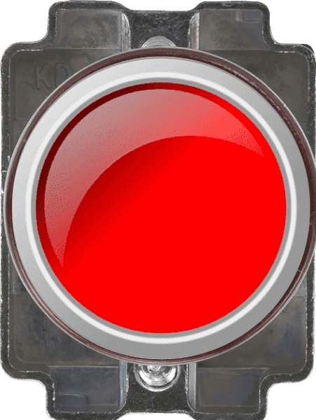
Push to ON
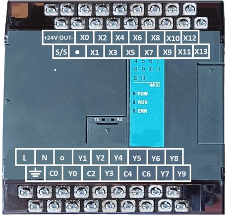
PLC
Supply


LED

MCB
Control circuit
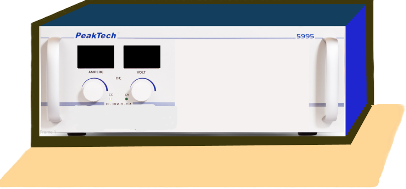
AC supply 3-phase 230v 50 Hz

PLC
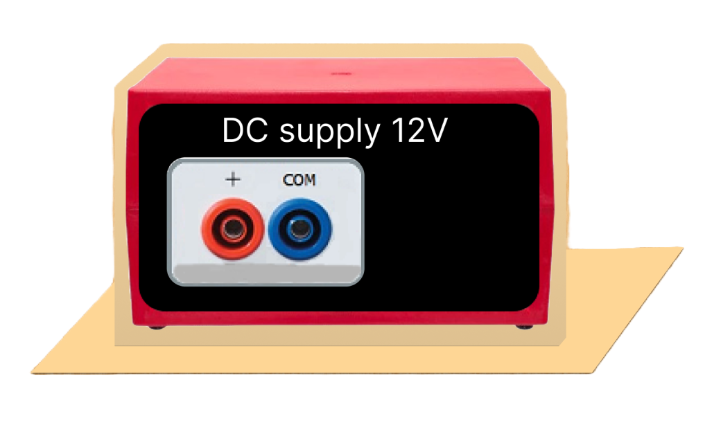
DC supply 12V

Stop

Start
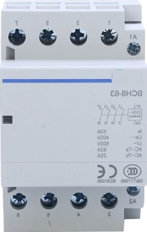
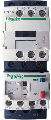
Contactor
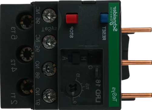
Overload Relay


LED
Power circuit
AC supply 3-phase 230v 50 Hz
MCB
Control Circuit

.png)
FAN (DC Motor)
Instructions
1. Click on the Control Circuit button in Control Circuit Section.
2. Get the required components in Control Circuit Section by clicking on components displayed in Components Section.
3. Establish the connections according to the control circuit diagram provided in Fig. (a).
4. Verify the control circuit by clicking on the Check Connections 1 button.
5. If Wrong Connections, click on the Delete Connections 1 button to delete connections and make the right connections.
6. Once the Control Circuit is verified, click on the PLC to design the ladder logic.
7. A new window will appear for the ladder logic. Design the ladder logic using the instructions tab on the PLC window.
8. Once the ladder logic is verified, switch to the Power Circuit Section. Make the connections according to the Power Circuit diagram provided in Fig. (b).
9. Click on the Check Connections 2 button to validate the Power Circuit.
10. If Wrong Connections, click on the Delete Connections 2 button to delete connections and make the right connections.
11. Once the Power Circuit is verified, switch on the Power Supplies & enable the Start Button by a clicking on them.
12. To stop circuit click on the Stop button.
13. To overload the current click on the ⚡ button which is located at the Overload relay.
14. Click on the Print button to get a print of the webpage.
15. Click on the Reset button to refresh the webpage.

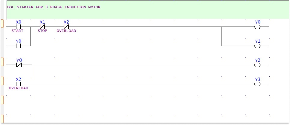
PLC Ladder Logic.
Components

NO (OFF)

NO (ON)

NC (OFF)

NC (ON)

Coil (OFF)

Coil (ON)
Y0

MOTOR
X0
START
X1
STOP
X2
OVERLOAD RELAY
Y0
Y1
ON Indicator
Y0
Y2
Stop Indicator
X2
OLR
Y3
Trip Indicator
To design a logic for starting a 3-phase Induction Motor by Direct on- Line (DOL) Starter.
1. Click on a black placeholder on the webpage to add a symbol.
2. A dialog will appear where you will write the symbol name (e.g., X0, X1, X2, Y0).
3. The symbol will be placed in the selected location according to the given diagram.
4. Repeat the process for each placeholder to complete the ladder logic as shown in the provided diagram.
5. If you make a wrong connection, click on the Delete Connections button to remove the wrong connection and make the correct one.
6. Click on the Check Connections button to verify that all connections are correct.
7. Ensure the connections follow the structure shown in the diagram
8. Verify your connections by comparing with the reference diagram.
9. Click on the Start Simulation and perform simulation