Introduction
The experiments of this lab are conducted on industrial electrical panels and the circuit diagram for these are divided into two parts: control circuit and power circuit. Power circuit is the main functioning circuit in which the load is connected. Control circuit is a low power circuit which typically contains controlling elements such as relays, counters or sensors and it manages the operation of the power circuit and the connected load. In this experiment, we aim to explore the principles of load control using switching relays by operating both a DC and an AC load. The Push-to-ON switch, also known as a momentary switch, is a fundamental component in electronics, providing temporary activation when it is pressed. Meanwhile, a switching relay is an electromechanical device which is used to control high power electrical components by low power signals.
● Push-to-ON switch:
In this experiment we are using a Push-to-ON switch. It is a NO (Normally Open) switch. It changes its state to NC (Normally Closed) when it is pressed. It is a momentary switch which means that it will change its state and remain in it until it is pressed only. As soon as it is released it will go back to its default state. Its mechanism involves a spring-loaded button that completes the circuit until it is kept pressed. By default, this button has red colour in the simulation and when it is pressed it turns green. Upon release, the switch returns to its default OFF state (Red colour).
● Switching relay:
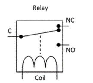
It is an electromechanical device used for switching and protection purposes in electrical systems. It comprises an electromagnetic coil and a set of contacts, including NO (Normally Open), NC (Normally Closed), and COM (Common). When the coil of the relay is energized, a magnetic field is generated in it and this magnetic field attracts the metallic strip, causing the NC contacts to become NO. These contacts can be connected in series with load to turn the load on or off. This ensures that the load circuit and control circuit are electrically isolated. The working of the single channel relay is shown in Fig.: 2 below.
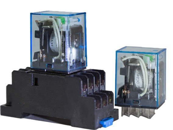
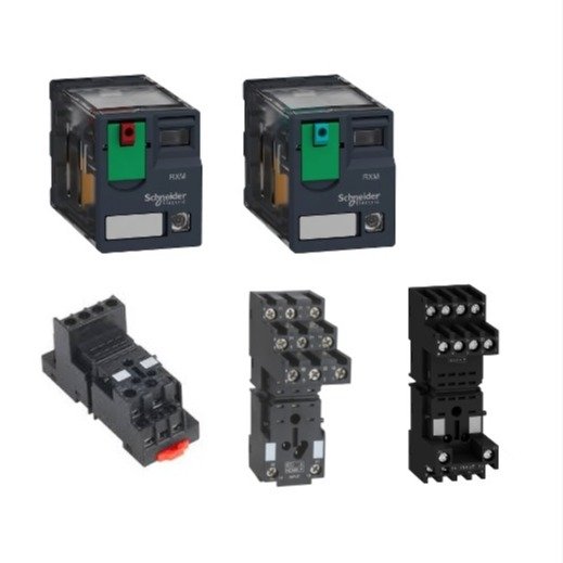
In this experiment we are using a four channel (4 C/O) relay. It is a plug-in relay which means that it is inserted in a base (a pre-wired socket). A relay is shown below in fig. (1). A four-channel relay has 4 terminals for Common, NC and NO each and 2 terminals for power supply (total 14 terminals).
About Experiment
Control circuit:
In this experiment two different circuits are used, as control circuits usually use low DC power supply and power circuits use high AC/DC power supply and they are not connected directly but are connected through contacts of relay.
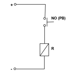
The control circuit consists of a Push-to-ON switch connected with the relay coil. When the Push to ON switch is pressed the circuit will be completed and now the flowing current will energize the relay coil. The moment the relay coil is energized, its contacts will change their states, and NO (normally open) contacts in the power circuit will become NC (normally closed), activating the load. The control circuit for this experiment is as shown in the given figure 4 below.
Power circuit:
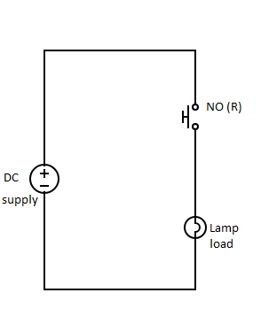
The power circuit consists of power supply and relay contacts in series with the load (AC and DC). The moment the relay coil is energized, its contacts will change their states, i.e. NO of the relay will become NC and hence the circuit will get closed and the loads will be turned on. The power circuit for this experiment is as shown in the figure 5 below.
DC load : The DC load is supplied by a DC source. The COM (common) terminal of the relay is connected to the positive of the power supply and the NO terminal of relay is connected to DC load. The other terminal of the DC load is connected to the negative terminal of the power source.
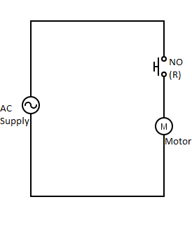
AC load: The AC load is supplied by a 230 V and 50 Hz AC source. One terminal of the load is connected to NO contact of Relay and the other terminal of load is connected to the neutral of the supply. The other terminal of the NO contact is connected to the phase of AC supply. AC load can be a motor, fan, etc