Procedure
Step 1: Click on the Control Circuit button in Control Circuit Section.
Step 2: Get the required components in Control Circuit Section by clicking on components displayed in Components Section.
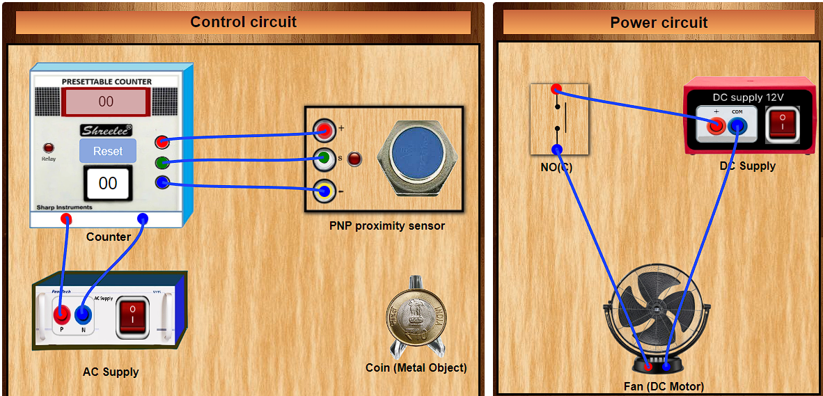
Step 3: Establish the connections according to the control circuit diagram provided.
Step 4: Verify the control circuit by clicking on the Check Connections 1 button.
Step 5: If Wrong Connections then click on Delete Connections 1 button to delete connections and make the right connections.
Step 6: Once the Control Circuit is verified, switch to the Power Circuit Section.
Step 7: Get the required components in Power Circuit Section by clicking on components displayed in Components Section.
Step 8: Make the connections according to the Power Circuit diagram provided.
Step 9: Click on the Check Connections 2 button to validate the Power Circuit.
Step 10: If Wrong Connections then click on Delete Connections 2 button to delete connections and make the right connections.
Step 11: Once the Power Circuit is verified, switch On the Power Supplies.
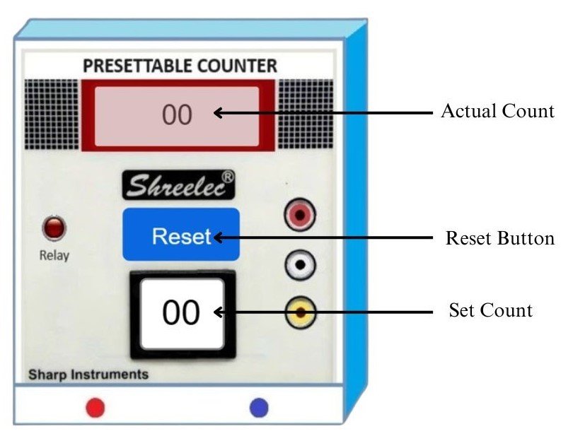
Step 12: Now enter the Count value (between 1-99) in the 'Set_Count' box.
Step 13: Then drag the Coin over the PNP proximity sensor , repeat this according to the count value set by you.
Step 14: To reset the 'Actual_Count' display value to "00", click on Counter's Reset button.
Step 15: To reset the 'Set_Count' box value to "00" , Switch OFF & ON the Power Supply buttons.