
Introduction
In multi-floor buildings, it is often necessary to control a single load, such as a fan or light, from multiple locations. A 3-way switch configuration allows this functionality by enabling the load to be turned on or off from three different floors. This experiment utilizes a Programmable Logic Controller (PLC) to implement the control logic required for such a setup, leveraging the flexibility and robustness of PLCs in industrial and commercial applications.
Programmable Logic Controller (PLC)
A PLC is an industrial digital computer designed for the control of manufacturing processes or robotic devices. Unlike general-purpose computers, the PLC is designed to be robust and reliable in industrial environments. It can be programmed to perform a wide variety of tasks based on input signals.
Control Circuit: The control circuit is responsible for processing the input signals from the switches (PB1, PB2, PB3) and generating an appropriate output to control the relay, which in turn controls the power circuit.
Power Circuit : The power circuit provides the necessary power to the load (fan) and is controlled by a relay which is activated or deactivated by the control circuit.
3-Way Switch Logic Using XOR:
In a 3-way switch configuration, the objective is to allow the control of a single load (fan) from three different switches, located on three different floors. This can be effectively achieved using XOR (exclusive OR) logic. The XOR logic ensures that the state of the load (on or off) changes every time any of the switches is pressed.
XOR Logic:
The XOR gate outputs true (1) only when an odd number of inputs are true.
In the context of a 3-way switch, the XOR logic can be used to toggle the state of the relay each time a switch is pressed, ensuring the load changes state accordingly.
Detailed Circuit Explanation :
Control Circuit
1. PLC Inputs: The push buttons (PB1, PB2, PB3) are connected to the PLC inputs (X0, X1, X2).
2. PLC Outputs: The PLC output (Y0) is connected to a relay coil.
3. Relay : The relay controls the power circuit based on the PLC output.

Power Circuit
1. DC Supply: Provides power to the fan.
2. Relay Contacts (NO): The normally open (NO) contacts of the relay close when the relay coil is energized, completing the circuit and powering the fan.
.
3. Fan (Load): The fan operates when the relay contacts are closed.

Ladder Logic Diagram
The ladder logic diagram for implementing the 3-way switch logic using XOR is shown below:
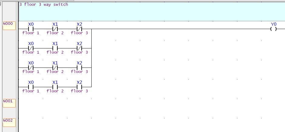
In this ladder logic diagram:
X0, X1, X2 represent the inputs from the push buttons on floors 1, 2, and 3, respectively.
Y0 represents the output to the relay controlling the fan.
Working of the Ladder Logic
1. The PLC continuously monitors the state of the push buttons (X0, X1, X2).
2. When any push button is pressed, the corresponding input to the PLC changes state.
3. The XOR logic implemented in the ladder diagram ensures that the output (Y0) toggles its state (from off to on or from on to off) every time any push button is pressed.
4. The relay coil connected to Y0 is energized or de-energized based on the state of Y0.
5. The relay contacts (NO) close or open, controlling the power to the fan and thus turning it on or off.
By utilizing XOR logic in the ladder diagram, the 3-way switch configuration allows any of the three push buttons to control the state of the fan, providing a flexible and efficient control mechanism suitable for multi-floor buildings.