
Introduction
DOL starting method involves direct switching of polyphase induction motor on to the supply mains. Since the DOL starter connects the motor directly to the main supply line, the motor draws a very high inrush current compared to the full load current of the motor (up to 5-8 times higher). The value of this large current decreases as the motor reaches its rated speed. If the supply system is of sufficient power capacity and the low power factor starting current surges don’t cause objectionable voltage dips in the supply line voltage, then the DOL starting should be preferred.
Introduction to Induction Motors
A 3-phase induction motor is a widely used type of electric motor that operates on the principle of electromagnetic induction. It consists of a stator, which is the stationary part of the motor, and a rotor, which rotates within the stator. When a 3-phase AC voltage is applied to the stator windings, a rotating magnetic field is produced, which induces a current in the rotor. This current generates a magnetic field that interacts with the stator's field, causing the rotor to turn and thus producing mechanical motion.
Need for a Direct-On-Line (DOL) Starter
Starting a 3-phase induction motor directly from the supply line without any intermediary device can lead to a high inrush current, which is typically 6 to 8 times the full load current. This inrush current can cause a significant voltage drop in the power supply network and may damage the motor windings, as well as other connected equipment. To mitigate these issues, a Direct-On-Line (DOL) starter is used.
A DOL starter connects the motor directly to the power supply but includes protective devices such as overload relays and contactors to ensure safe operation. The primary purpose of a DOL starter is to provide a straightforward, cost-effective method for starting the motor while protecting it from overcurrent conditions.
Direct-On-Line (DOL) Starter
A DOL starter is a method of starting electric motors by applying the full line voltage directly to the motor terminals. It includes a main contactor, an overload relay for motor protection, and start/stop push buttons for control. When the start button is pressed, the contactor closes, and the motor is connected to the power supply, starting immediately. The overload relay protects the motor from excessive current.
Components of a DOL Starter
1 . Main Contactor: This is an electromechanical switch that connects the motor to the power supply. It is controlled by the PLC or manual push buttons.
2 . Overload Relay: This device protects the motor from overcurrent conditions by disconnecting the motor from the supply if the current exceeds a preset limit.
3. Start and Stop Buttons: These buttons are used to manually control the operation of the motor. The start button energizes the main contactor, while the stop button de-energizes it.
4 .PLC (Programmable Logic Controller): The PLC processes input signals from the start and stop buttons and controls the operation of the contactor and overload relay.
Control Circuit
The control circuit for a DOL starter typically involves the use of push buttons, relays, and contactors. In this experiment, a PLC is used to implement the control logic, enhancing flexibility and control over the motor starting process.

Power Circuit
The power circuit includes the main contactor that connects the motor to the power supply and the overload relay that provides protection against overcurrent conditions.

Detailed Circuit Explanation
Control Circuit
1. PLC Inputs: The start and stop push buttons are connected to the
PLC inputs.
2. PLC Outputs: The PLC output is connected to the main contactor
coil.
3. Relay and Contactor: The relay controls the main contactor based
on the PLC output.
Power Circuit
1. 3-Phase Power Supply: Provides the necessary power to the
induction motor.
2. Main Contactor: Connects the motor to the power supply when
energized.
3. Overload Relay: Protects the motor from overcurrent by
disconnecting it from the power supply if excessive current is
detected.
4. Motor: The 3-phase induction motor that is being controlled.
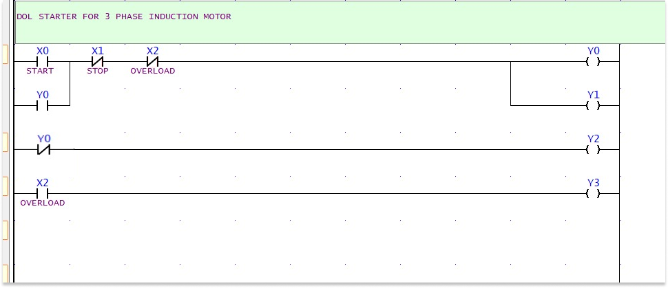
Ladder Logic Diagram for DOL Starter
The ladder logic diagram for implementing the DOL starter is shown below:
Applications of DOL Starter
1 .Industrial Machinery: DOL starters are commonly used to start motors in various industrial applications, such as conveyor belts, compressors, and pumps.
2. HVAC Systems: Heating, ventilation, and air conditioning systems often use DOL starters to manage the operation of large fans and blowers.
3. Agricultural Equipment: DOL starters are used in agricultural machinery like irrigation pumps and grain augers, where reliable motor control is essential.
4 .Water Treatment Plants: Motors driving water pumps in treatment plants are frequently started using DOL starters to ensure efficient and controlled operation.
In summary, a DOL starter provides a simple and effective method to start and control a 3-phase induction motor, ensuring safe operation and protecting the motor from potential damage due to high inrush currents and overcurrent conditions. The use of a PLC in the control circuit enhances programmability and offers additional protection features, making it a versatile solution for various industrial and commercial applications.