Procedure
Step 1: Click on the Control Circuit button in Control Circuit Section.
Step 2: Get the required components in Control Circuit Section by clicking on components displayed in Components Section.
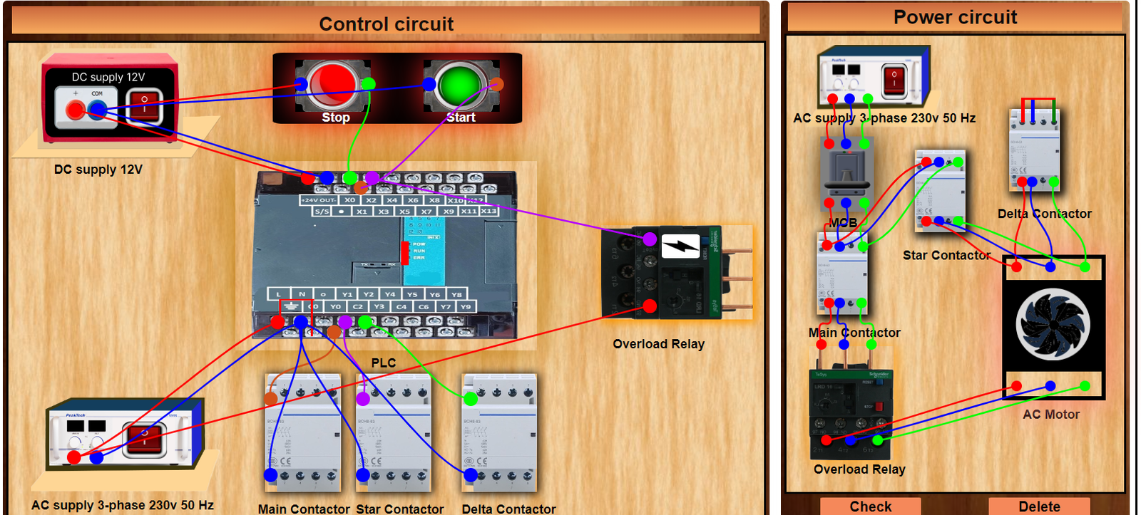
Step 3: Establish the connections according to the control circuit diagram provided in Fig. (a).
Step 4: Verify the control circuit by clicking on the Check Connections 1 button.
Step 5: If Wrong Connections, click on the Delete Connections 1 button to delete connections and make the right connections.
Step 6: Once the Control Circuit is verified, click on the PLC to design the ladder logic.
Step 7: A new window will appear for the ladder logic. Design the ladder logic using the instructions tab on the PLC window.
Step 8: Once the ladder logic is verified, switch to the Power Circuit Section. Make the connections according to the Power Circuit diagram provided in Fig. (b).
Step 9: Click on the Check Connections 2 button to validate the Power Circuit.
Step 10: If Wrong Connections, click on the Delete Connections 2 button to delete connections and make the right connections.
Step 11: Once the Power Circuit is verified, switch on the Power Supplies & enable the Start Button by a clicking on them.
Step 12: To stop circuit click on the Stop button.
Step 13: To overload the current click on the ⚡ button which is located at the Overload relay.
Step 14: Click on the Print button to get a print of the webpage.
Step 15: Click on the Reset button to refresh the webpage.