Procedure
Step 1: Click on the 'Control Circuit button' in Control Circuit Section.
Step 2: Get the required components in Control Circuit Section by clicking on components displayed in Components Section.
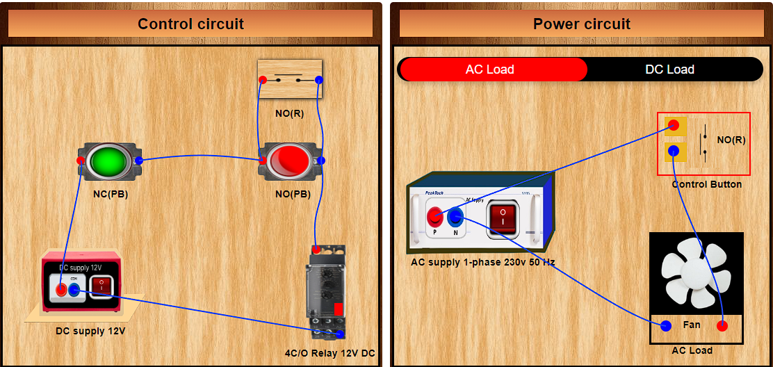
Step 3: Establish the connections according to the control circuit diagram provided in Fig.4.
Step 4: Verify the control circuit by clicking on the 'Check Connections 1 button.'
Step 5: If Wrong Connections then click on 'Delete Connections 1 button' to delete connections and make the right connections .
Step 6: Once the Control Circuit is verified, switch to the Power Circuit Section, Choose between AC Load & DC Load .
Step 7: Get the required components in Power Circuit Section by clicking on components displayed in Components Section.
Step 8: Make the connections according to the Power Circuit diagram provided in Fig. 5 and Fig. 6.
Step 9: Click on the 'Check Connections 2 button' to validate the Power Circuit.
Step 10: If Wrong Connections then click on 'Delete Connections 2 button' to delete connections and make the right connections .
Step 11: Once the Power Circuit is verified, Switch On the Power Supplies & Enable the 'Push Button' by a mouse hover to turn the load ON.
Step 12: To turn the load OFF, enable the 'OFF Push button' by a mouse hover.
Step 13: Click on the 'Print button'to get a print of the webpage.
Step 14: Click on the 'Reset button' to refresh the webpage.