Introduction
In this experiment, we aim to explore the principles of load control with holding using switching relays and a holding circuit. The push-to-ON & OFF switch, is a momentary switch, so to run the load we have to keep the push button pressed continuously. So, to hold the load in its ON condition without needing to keep the push button pressed we are using a holding circuit in this experiment.
● Push-to-ON switch:
In this experiment we are using a Push-to-ON switch. It is a NO (Normally Open) switch. It changes its state to NC (Normally Closed) when it is pressed. It is a momentary switch which means that it will change its state and remain in it until it is pressed only. As soon as it is released it will go back to its default state. Its mechanism involves a spring-loaded button that completes the circuit until it is kept pressed. By default, this button has red colour in the simulation and when it is pressed it turns green. Upon release, the switch returns to its default OFF state (Red colour).
● Push-to-OFF switch:
In this experiment we are using a push-to-OFF switch for turning the load OFF. It is a NC (Normally Closed) switch. It changes its state to NO (Normally Open) when it is pressed. It is a momentary switch which means that it will change its state and remain in it until it is pressed only. As soon as it is released it will go back to its default state. Its mechanism involves a spring-loaded button that completes the circuit until it is kept pressed. By default, this button has green colour in the simulation and when it is pressed it turns red. Upon release, the switch returns to its default OFF state (Green colour).
● Switching relay:
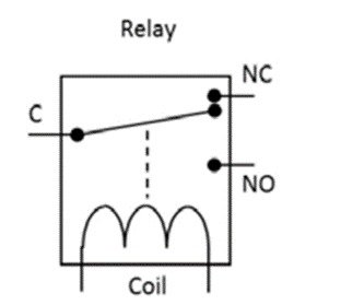
It is an electromechanical device used for switching and protection purposes in electrical systems. It comprises an electromagnetic coil and a set of contacts, including NO (Normally Open), NC (Normally Closed), and COM (Common). When the coil of the relay is energized, a magnetic field is generated in it and this magnetic field attracts the metallic strip, causing the NC contacts to become NO. These contacts can be connected in series with load to turn the load on or off. This ensures that the load circuit and control circuit are electrically isolated. The working of the single channel relay is shown in Fig.: 2 below.
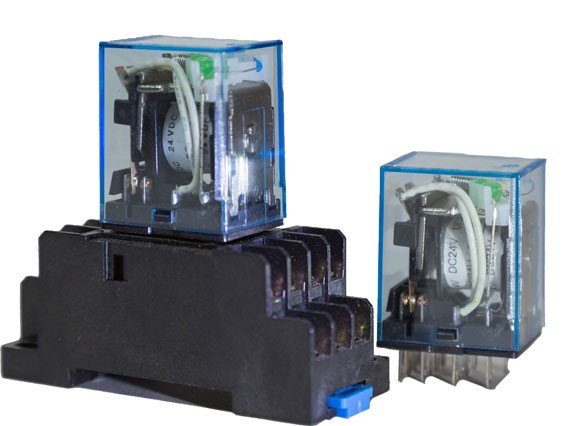
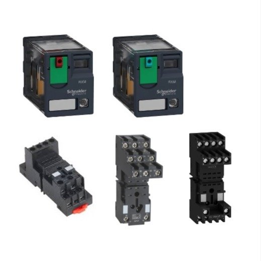
In this experiment we are using a four channel (4 C/O) relay. It is a plug-in relay which means that it is inserted in a base (a pre-wired socket). A relay is shown in fig. (1). A four-channel relay has 4 terminals for Common, NC and NO each and 2 terminals for power supply (total 14 terminals).
About Experiment
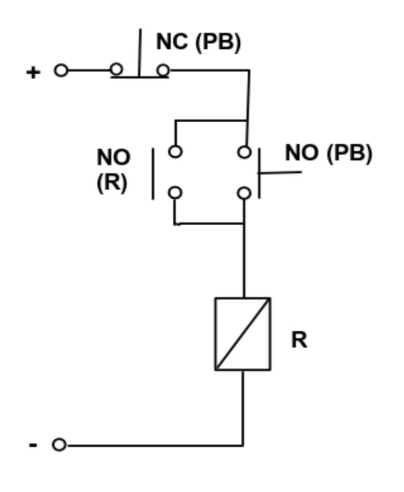
Control circuit:
The control circuit of this experiment consists of a push-to-ON and a push-to-OFF switch in series with the coil of the relay. When a momentary switch is used it should be pressed continuously for the load to run continuously, which means that a push-to-ON switch allows current to flow only until it is kept pressed. So to run the load continuously, without needing to keep the push-to-ON switch pressed, we are using a holding circuit which allows the flow of current even when the push-to-ON switch is released.
1. Activation of the relay: The push-to-ON switch is used to turn the load ON. When the push-to-ON switch is pressed, it momentarily completes the circuit. This allows current to flow through the relay coil and energize it. As the relay gets energized its contacts change their state and the NO contacts get closed. These closed contacts power both the AC and DC load. Simultaneously, the holding circuit is activated.
2. Maintaining of the relay state (Holding circuit): The holding circuit consists of a NO contact of relay in parallel with the push-to-ON switch. When we press the push-to-ON switch the coil gets energized. After the coil gets energized, the NO contact of the relay in parallel with the push-to-ON switch becomes NC immediately. This NC will now go back to its default state (NO) only when the relay is de-energized. Now, when we release the push-to-ON switch the circuit is completed by that NC contact. Hence, the circuit remains closed even after releasing the push button. In this way holding of the relay in ON state is achieved.
3. Deactivation of the relay: The push-to-OFF switch is used to turn the load OFF. When this switch is not pressed it remains in NC (Normally Closed) state and when it is pressed it becomes NO (Normal Open) due to which the circuit opens and the relay coil gets de-energized. As the coil of relay gets de-energized its NC contact in parallel with the push button becomes NO and hence the circuit opens, turning the load OFF.
Power circuit:
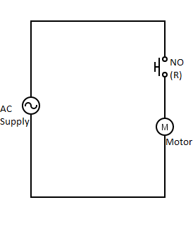
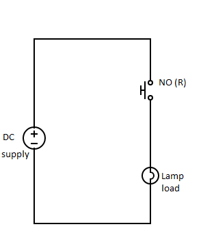
The power circuit of this experiment consists of NO contact of relay in series with the load (AC/DC). When the relay is energized this NO contact becomes NC which completes the circuit and turns ON the load.
To turn the load OFF, push-to-OFF switch is pressed. It becomes NO (Normally Open) when it is pressed due to which the control circuit becomes open and the relay coil gets de-energized.
DC load : The DC load is supplied by a DC source. The COM (common) terminal of the relay is connected to the positive of the power supply and the NO terminal of relay is connected to DC load. The other terminal of the DC load is connected to the negative terminal of the power source.
AC load: The AC load is supplied by a 230 V and 50 Hz AC source. One terminal of the load is connected to NO contact of Relay and the other terminal of load is connected to the neutral of the supply. The other terminal of the NO contact is connected to the phase of AC supply. AC load can be a motor, fan, etc