
Introduction
Operating a DC motor in both forward and reverse directions is
essential in various applications such as robotics, conveyors, and
automation systems. This experiment demonstrates the control of a DC
motor's direction using two switching relays and an interlocking
circuit. The interlocking circuit is crucial as it prevents the
simultaneous activation of both relays, which could result in a
short circuit and damage the motor.
Direction Control of DC Motor
The direction of rotation of a DC motor is controlled by reversing the polarity of the voltage applied to the armature. This reversal can be achieved using relays, which are electrically operated switches. By configuring the relay connections, the direction of current flow through the motor can be changed, thereby reversing its rotation direction.
DC motors operate on the principle that when an electric current passes through a coil in a magnetic field, it experiences a force that causes it to rotate. The direction of rotation depends on the direction of the current flow through the motor's armature windings. By reversing the current flow, the direction of the magnetic field interaction changes, thereby reversing the motor's direction of rotation. This capability is particularly useful in applications requiring precise bidirectional control.
Relays and Interlocking
Relay
An electromagnetic switch used to control a high-power circuit with
a low-power signal. A relay consists of a coil, an armature, a
spring, and a set of electrical contacts. When the coil is energized
by a control signal, it generates a magnetic field that attracts the
armature, causing the contacts to either open or close, thereby
switching the connected circuit.
Interlocking
A safety mechanism ensuring one action prevents another, thereby
avoiding unsafe conditions. In this experiment, interlocking
prevents both relays from being activated simultaneously, thus
avoiding a short circuit or damage to the motor. Interlocking is
achieved by wiring the NC (Normally Closed) contacts of each relay
in series with the coil of the opposite relay. This setup ensures
that when one relay is activated, it opens the NC contacts of the
other relay, preventing it from being energized.
Components Used
1. NO (Normally Open) Push Button :
When pressed, the circuit is completed, allowing current to flow. Used to initiate the motor's operation in either forward or reverse direction.
2. NC (Normally Closed) Push Button :
When pressed, the circuit is opened, interrupting current flow. Used for emergency stop or switching off the motor.
3. 4C/O Relay (RXM2LB2JD) :
A four changeover relay that can control multiple circuits and is activated by a 12V DC control signal. The relay's contacts can be configured to switch between different circuits, making it suitable for reversing the polarity of the motor's power supply.
4. DC Motor (12V) :
The motor to be controlled for forward and reverse operation. A 12V
DC motor is commonly used in various applications due to its
compatibility with low-voltage power supplies and its ability to
provide sufficient torque and speed for many tasks.
Circuit Operation
Control Circuit
The control circuit involves two push buttons and two relays. Each
push button controls one relay. The interlocking mechanism ensures
that only one relay can be active at any time.
- Forward Direction :
- When the NO push button for forward direction is pressed, it
energizes the corresponding relay.
- The relay's contacts close, allowing current to flow through the
motor in the forward direction.
- Reverse Direction :
- When the NO push button for reverse direction is pressed, it
energizes the corresponding relay.
- The relay's contacts close, reversing the current flow through the
motor, thus changing its direction.
- Interlocking Mechanism :
- The NC contacts of each relay are connected in series with the
coil of the opposite relay.
- This setup prevents both relays from being energized
simultaneously, avoiding a short circuit.
Power Circuit
The power circuit is directly connected to the motor and the relays.
It provides the necessary voltage and current to drive the motor in
the desired direction.
- Forward Direction :
- The relay for the forward direction connects the positive terminal
of the power supply to one terminal of the motor and the negative
terminal to the other.
- Reverse Direction :
- The relay for the reverse direction swaps the connections,
reversing the current flow through the motor.
Schematic Diagram
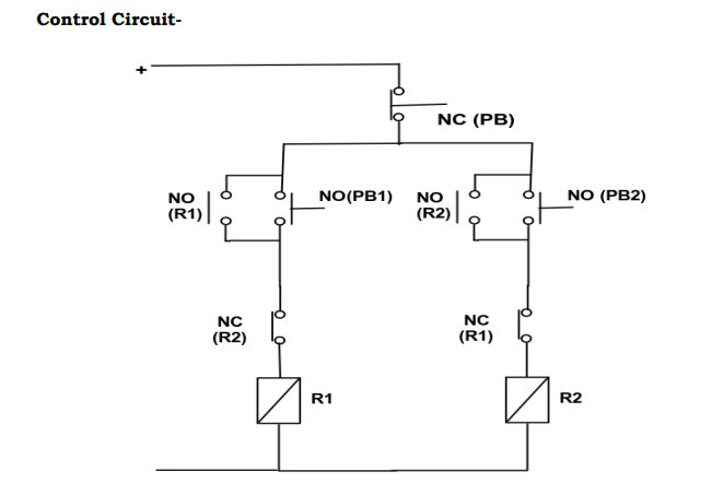
The control circuit's primary function is to determine which relay is activated based on the push button pressed. When the forward push button is pressed, the forward relay is energized, completing the circuit for the motor to run in the forward direction. Conversely, pressing the reverse push button energizes the reverse relay, altering the polarity of the voltage applied to the motor and causing it to run in the reverse direction. The interlocking mechanism is essential for ensuring the safe operation of the motor. By using the NC contacts of each relay in series with the coil of the opposite relay, the circuit ensures that activating one relay automatically disables the other. This prevents both relays from being energized simultaneously, which could create a direct short circuit across the power supply and potentially damage the motor and relays.
Control Circuit Diagram
The control circuit diagram shown in Fig.(1) includes the push buttons, relays, and interlocking connections. It shows how the NO and NC contacts are wired to achieve the desired control and safety features.
Power Circuit Diagram
The power circuit diagram as shown in Fig.(2) illustrates the connections between the power supply, relays, and motor. It demonstrates how the relays switch the polarity of the voltage applied to the motor for forward and reverse operation.
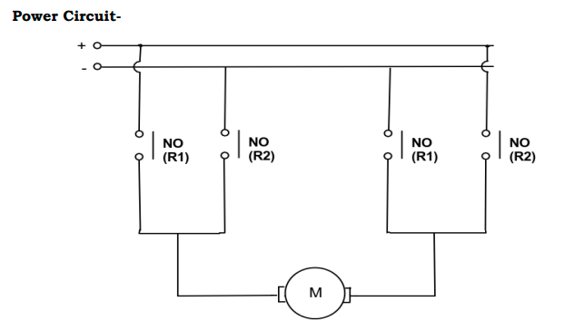
The interlocking mechanism is crucial in preventing simultaneous activation of conflicting relays, thereby protecting the motor and control circuitry. By using two switching relays with interlocking, the DC motor can be safely and effectively operated in both forward and reverse directions. This principle is widely used in industrial applications where precise control of motor direction is required.
Practical Applications and Importance
The ability to control the direction of a DC motor using relays and an interlocking mechanism is essential in various practical applications. In robotics, for example, precise control of motor direction allows for accurate movement and positioning of robotic arms and wheels. In conveyor systems, the ability to reverse motor direction is crucial for tasks such as sorting and redirecting items. Automation systems also benefit from this control, enabling machinery to operate efficiently and safely in both directions. The interlocking mechanism's importance extends beyond preventing short circuits; it also enhances the overall reliability and safety of the system. By ensuring that only one relay is activated at a time, the interlocking mechanism reduces the risk of electrical faults and mechanical failures, thereby improving the longevity and performance of the motor and control components.