Procedure
Step 1: Click on the Control Circuit button in Control Circuit Section.
Step 2: Get the required components in Control Circuit Section by clicking on components displayed in Components Section.
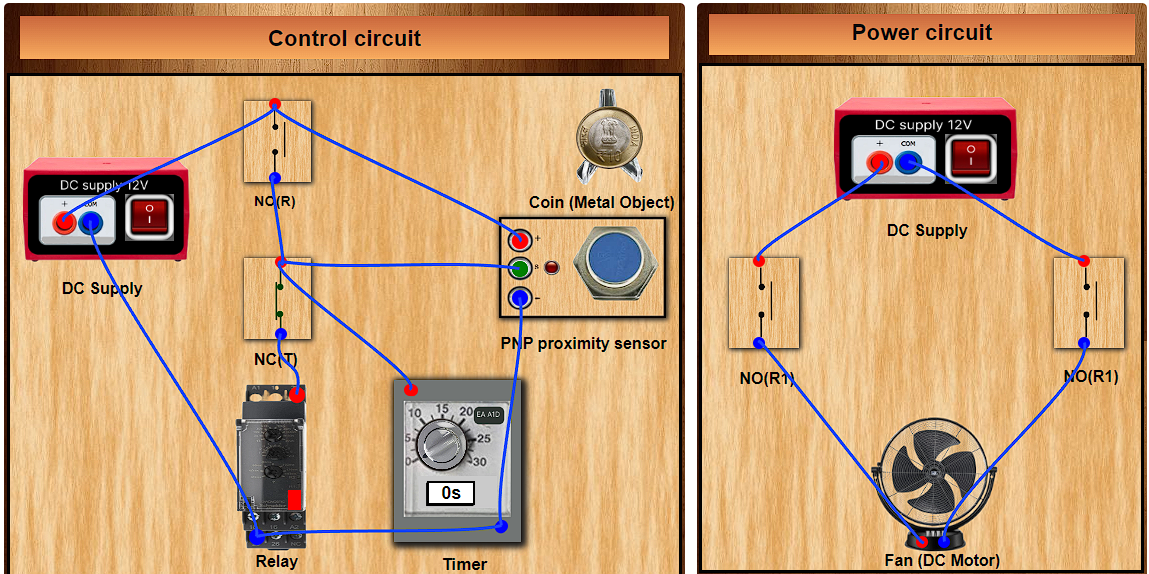
Step 3: Establish the connections according to the control circuit diagram provided.
Step 4: Verify the control circuit by clicking on the Check Connections 1 button.
Step 5: If Wrong Connections then click on Delete Connections 1 button to delete connections and make the right connections.
Step 6: Once the Control Circuit is verified, switch to the Power Circuit Section , Choose between AC Load & DC Load.
Step 7: Get the required components in Power Circuit Section by clicking on components displayed in Components Section.
Step 8: Make the connections according to the Power Circuit diagram provided.
Step 9: Click on the Check Connections 2 button to validate the Power Circuit.
Step 10:. If Wrong Connections then click on Delete Connections 2 button to delete connections and make the right connections.
Step 11:. Once the Power Circuit is verified, switch On the Power Supplies.
Step 12:. Now set the Timer value (between 1-30sec) by rotating the timer knob.
Step 13:. Then drag the Coin on the PNP proximity sensor to start the motor with timer countdown (motor stops when countdown ends).
Step 14:. Click on the Print button to get a print of the webpage.
Step 15: Click on the Reset button to refresh the webpage.