
Introduction
The experiment involves controlling a DC load using a proximity sensor and a timer. It demonstrates the integration of sensing and timing functionalities to control a DC load, such as a motor or light, based on the presence of an object detected by a proximity sensor. In this experiment an inductive type proximity sensor is used to detect metallic objects and the timer circuit is used to stop the DC load.
Proximity sensor: A proximity sensor is a device that can detect or sense the approach or presence of nearby objects without being in physical contact with the object. The proximity sensor generates a signal when it detects an object within its sensing range. This signal can be digital (High/Low) or analog (Continuous). For this experiment, a digital inductive type proximity sensor is used.
There are different kinds of proximity sensors. Some of them are listed below-:
1. Inductive: This type of sensor detects nearby metallic objects. The sensor creates an electromagnetic field around itself or on a sensing surface.
2. Capacitive: This type of sensor is used for detection of metallic objects and non-metallic objects.
3. Photoelectric: This type of sensor is used to detect objects. A light source and receiver are the main components of such sensors.
4. Magnetic: - This type of sensor uses an electrical switch that is operated based on the presence of permanent magnets in a sensing area.
Most industrial proximity sensors (inductive, capacitive, ultrasonic and photo electric) are solid state.
The term solid state refers to the electronic components such as transistors used to switch the output of the sensor upon detection of an object.
Two specific types of 3 wire sensors are available; PNP and NPN.
1. PNP proximity sensors: PNP proximity sensors provide an active HIGH output. When an object enters the detecting range of the sensor, the output of the sensor is connected with +24V. It is also called ‘sourcing’ proximity sensor as it provides a positive voltage (source) when it senses an object.
2. NPN proximity sensors: NPN proximity sensors provide an active LOW output. This means that when an object enters the detecting range of the sensor, the output of the sensor is connected with the ground. It is also called ‘sinking’ proximity sensor as it provides zero voltage when it senses an object."
Basic connection of both PNP and NPN proximity sensor are as shown in figure 1 and 2 respectively.
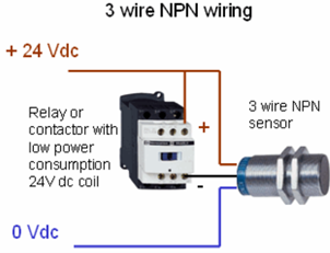
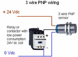
An inductive proximity sensor has three terminals- two for power supply of sensor (positive and negative) and one for output signal of sensor. When the sensor senses a metallic object a positive voltage (High signal) is generated on the signal pin of the sensor. The load is always connected between this signal pin and ground of power supply (for PNP sensor). So, when the sensor senses a metallic object, the load gets a positive voltage from the signal pin of the sensor which completes the circuit and turns the load on. Note, that the signal pin gives output only until the sensor senses a metallic object. As soon as the metallic object is removed, the output of the signal terminal vanishes.
Working Principle
1. Proximity Detection: The proximity sensor continuously monitors for the presence of an object within its detection range. When an object is detected, the sensor outputs a signal, typically a voltage change.
2. Signal Processing: The output signal from the proximity sensor is fed into a timer circuit. The timer circuit processes this signal to initiate a time delay or to control the duration for which the DC load remains activated."
3. Activation of DC Load: Based on the timer settings, the timer circuit sends a control signal to a relay or a transistor switch connected to the DC load. The DC load is then powered on or off according to the predefined timing conditions.
Circuit Design and Implementation
1. Proximity Sensor Interface: Connect the proximity sensor to the input of the timer circuit. Ensure proper power supply and grounding for stable operation.
2. Timer Configuration: Configure the timer circuit (e.g., using a 555 Timer IC in monostable mode) to define the desired delay or activation period.
3. Control Mechanism: Use a relay or transistor as a switch to control the DC load based on the output from the timer circuit.
4. 4. Power Supply: Ensure an adequate and stable DC power supply for both the sensor and the timer circuit.
Advantages of proximity sensor and timer
1. Energy Efficiency: Reduces energy consumption by ensuring that DC loads operate only when necessary.
2. Automation: Enhances the convenience and safety of automated systems by eliminating the need for manual operation.
3. Extended Device Life: By limiting the operational time of DC loads, wear and tear are reduced, potentially extending the life of the devices.
Applications of proximity sensor and timer
1. Automatic Lighting Systems: Lights can be automatically turned on when someone enters a room and turned off after a specified period of no motion detected.
2. Industrial Automation: Machinery can be activated when an object or material is detected and can be turned off after a specific time.
3. Security Systems: Alarms can be triggered or cameras can be activated when movement is detected within a restricted area.
Conclusion
The integration of a proximity sensor and a timer circuit for operating a DC load provides an effective solution for automating various applications. The combination of sensor-based detection and precise timing control enhances operational efficiency and energy savings, making it a valuable approach in modern automation systems.
This theory provides a comprehensive understanding of how a DC load can be controlled using a proximity sensor and a timer circuit, highlighting the essential components, working principles, and practical applications of the system.