Procedure
Strep 1: Select the logic gate for which you want to implement.
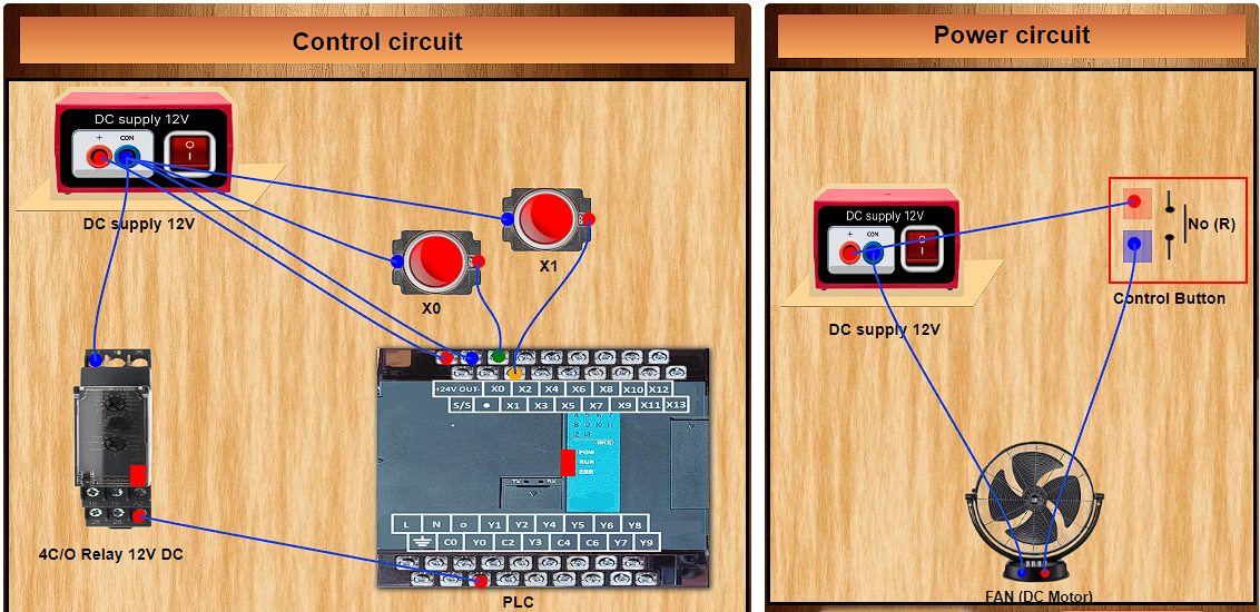
Step 2: Click on the 'Control Circuit' button in Control Circuit Section and get the required components by clicking on them.
Step 3: Establish the connections according to the control circuit diagram as shown in fig.a in the Instructions tab.
Step 4: Verify the control circuit by clicking on the 'Check Connections 1' button.
Step 5: If Wrong Connections then click on 'Delete Connections 1 button' to delete connections and make the right connections .
Step 6: Once the Control Circuit is verified, switch to the Ladder logic program by clicking on the PLC in Control circuit section.
Step 7: Read the instructions carefully and make the Ladder logic according to the figure given in the instruction tab.
Step 8: Click on the 'Start simulation' button to start the simulation.
Step 9: Click on the NO/NC button to change its state.
Step 10: Now you can move on to make the Power circuit. Click on the cross button to go back to the Power circuit section. Click on 'Power circuit' button and then select the components from the components section.
Step 11: Make the connections according to the power circuit diagram shown in fig.b in instructions tab.
Step 12: Verify the power circuit by clicking on the ‘Check connections 2’ button.
Step 13: If Wrong Connections then click on 'Delete Connections 2' button to delete connections and make the right connections .
Step 14: Once the Power circuit is verified, switch on the power supplies of control circuit and power circuit.
Step 15: When the push-to-ON switch is not clicked it gives logic 0 or Low signal to the PLC input and when you click on the push-to-ON button it gives a logic 1 or High signal to the PLC input. In this way you can make combination of 0's and 1's and verify the truth table of the logic gate selected.